Don't Lose Your Cool: The Ultimate Ecobee Thermostat Premium Installation Setup
ecobee Thermostat Premium Installation: A Quick Start for Homeowners
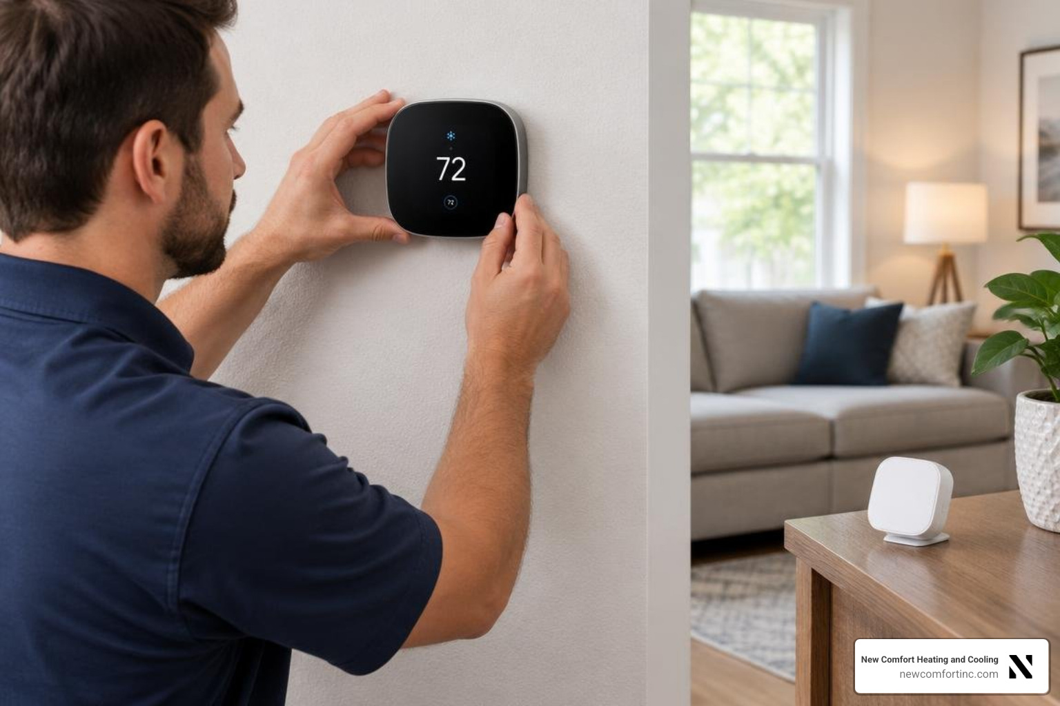
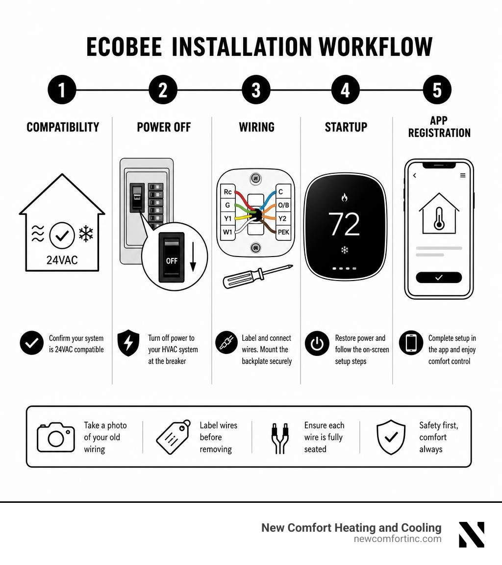
ecobee thermostat premium installation usually takes about 45 minutes in a typical home with a compatible 24VAC HVAC system. The basic process is simple: confirm compatibility, shut off HVAC power, label and connect the wires, mount the backplate, then follow the on-screen and app setup steps.
Before you begin, check these essentials:
- Your system uses low-voltage 24VAC controls, not 120V or 240V line voltage.
- You have a C-wire, or at least four usable wires for the included Power Extender Kit (PEK).
- You turn off power to the furnace or air handler at the breaker before touching any wiring.
- You photograph and label the old thermostat wires before removing them.
- You verify each wire is fully seated in the ecobee backplate before restoring power.
A correct installation helps your thermostat control heating, cooling, and fan operation reliably. It also avoids common problems, such as a blank screen, an HVAC safety switch left open, or wires connected to the wrong terminals.
This guide walks through the key checks, wiring paths, PEK setup, startup steps, and no-power troubleshooting homeowners need before relying on their new thermostat.
Pre-Installation Checklist: Compatibility, Tools, and Box Contents
Before unscrewing your old thermostat from the drywall, we recommend opening up your new ecobee box and laying out all included hardware alongside your hand tools. Taking inventory takes only a couple of minutes and saves you from unexpected trips to the hardware store mid-project.
Inside the package, you will find:
- ecobee Smart Thermostat Premium smart faceplate
- Thermostat backplate featuring quick-connect terminal blocks
- Power Extender Kit (PEK) for systems lacking a C-wire
- SmartSensor with detachable stand and wall-mounting bracket
- Trim plate (optional plate to hide paint lines or wall blemishes)
- Drywall anchors and mounting screws
- Pre-printed wire label sheet
- Quick Start manual and setup reference
You will need a few simple tools from your home toolkit: a Phillips-head screwdriver, a small flathead screwdriver (or precision driver), a level, and a power drill equipped with a 3/16-inch drill bit if you are installing new drywall anchors. Keep a pencil and wire strippers handy just in case old wire ends are frayed or damaged.
| Wire Label | Common Wire Color | Function & HVAC Control Purpose |
|---|---|---|
| Rc | Red | 24VAC Cooling Power Supply (Main Power) |
| Rh | Red | 24VAC Heating Power Supply (Jumpered internally on ecobee) |
| C | Blue / Black | 24VAC Common Wire (Provides continuous power return path) |
| Y1 | Yellow | Stage 1 Compressor Control (Cooling / Primary Compressor) |
| Y2 | Yellow / Brown | Stage 2 Compressor Control (High-stage cooling) |
| W1 | White | Stage 1 Heating Control (Furnace / Auxiliary Heat) |
| W2 | White / Pink | Stage 2 Heating Control (High-stage heat) |
| G | Green | Indoor Fan Blower Control |
| O/B | Orange / Dark Blue | Reversing Valve Control for Heat Pump Systems |
| ACC+ / ACC- | Varies | Accessory Terminal (Humidifiers, Dehumidifiers, Ventilators) |
Checking HVAC Compatibility and C-Wire Requirements
Safety comes first whenever working with residential HVAC electronics. The ecobee Smart Thermostat Premium is designed specifically for standard low-voltage 24VAC systems with a maximum current limit of 2 Amps. It is natively compatible with conventional heating and cooling setups (up to 2 stages of heating and 2 stages of cooling) as well as heat pump configurations (up to 4 stages of heating and 2 stages of cooling).
It is strictly incompatible with high-voltage line systems (such as 110V, 120V, or 240V electric baseboard heaters) and solid-state millivolt systems (often found in standalone gas fireplaces or gravity furnaces). Attempting an ecobee thermostat premium installation on a line-voltage circuit will instantly damage the thermostat and poses a major risk of electrical fire or personal injury.
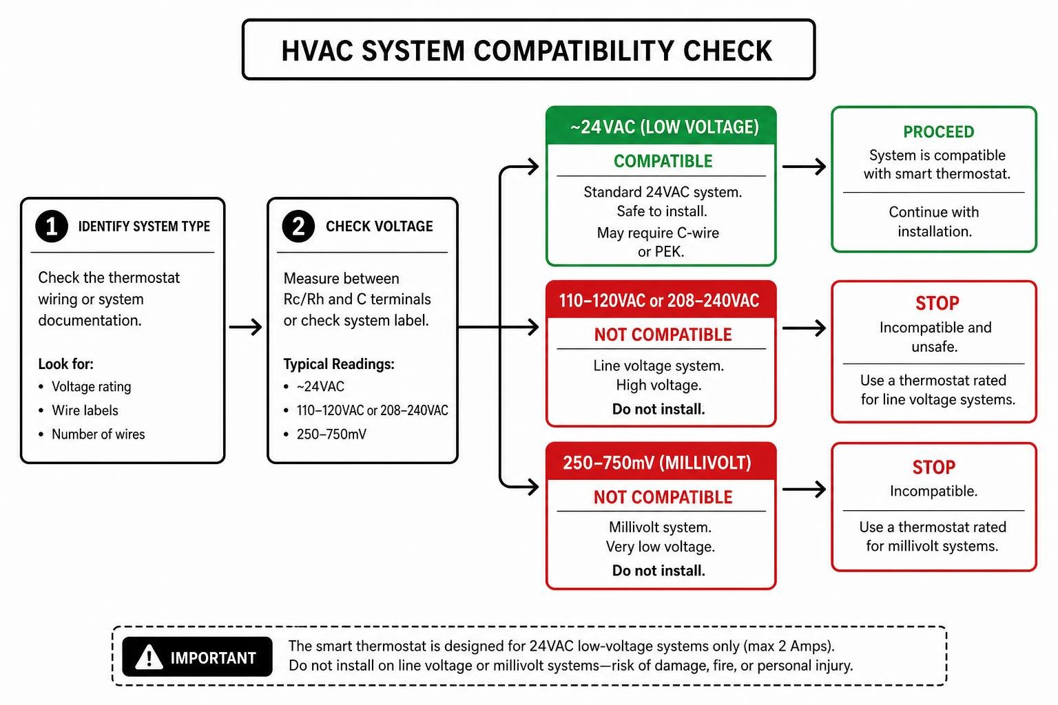
To operate modern smart features, internal radar sensors, and vibrant touchscreens, smart thermostats require a continuous supply of 24VAC electrical power. This constant circuit is powered by the C-wire (Common wire). While older mechanical thermostats used alkaline batteries or relied on battery power to click simple relays, smart devices need the C-wire to complete a continuous power loop alongside the Rc (Red) wire.
If you pop off your existing thermostat faceplate and see a wire connected to a terminal labeled "C", you have a dedicated C-wire! If there is no wire connected to C, do not panic—we can easily supply constant power using the included Power Extender Kit (PEK). For extra safety details regarding low-voltage system checks, consult the Official ecobee Support Resource.
Preparing for ecobee Thermostat Premium Installation
Once you have verified system compatibility, prepare your workspace using these safety steps:
- Cut Main Power: Head to your home's main electrical breaker panel and switch off power to your heating and cooling equipment. In many homes across Chicago, IL, and Justice, IL, there is also a secondary toggle switch located directly on or near the side of the furnace unit. Flip that switch off too.
- Verify Power Disconnection: Walk back to your old thermostat and attempt to turn on the heat or air conditioning. Wait at least two minutes to confirm that neither the indoor blower fan nor the outdoor AC compressor turns on. If the thermostat display remains active or the fan kicks on, return to the breaker box and switch off the correct breaker before touching any wires!
- Photograph Existing Wiring: Carefully pop the old thermostat cover off its backplate. Before unscrewing a single wire, pull out your smartphone and take a crisp, clear photo of the connected wires and terminal labels. This photo serves as your safety net if you ever need to reference original wire placement.
- Tag Every Wire: Use the sticker sheet provided in the ecobee box to label each wire according to the letter on the terminal block it is currently connected to—not by wire color alone. Wire colors used by original builders are not always standard.
- Disconnect and Secure: Unscrew the wires from the old backplate and remove the old assembly from the wall. Gently wrap or tape the wire ends together or wrap them loosely around a pencil so they do not slide back inside the wall opening.
- Prep the Backplate: Hold the new ecobee backplate against the wall, feeding the labeled wire bundle through the center hole. Use a built-in level or small torpedo level to make sure the plate sits perfectly straight. Mark your mounting screw holes with a pencil. If you are drilling into bare drywall, drill two holes using a 3/16-inch drill bit and tap the drywall anchors flush with your wall surface using a hammer.
Step-by-Step ecobee Thermostat Premium Installation Guide
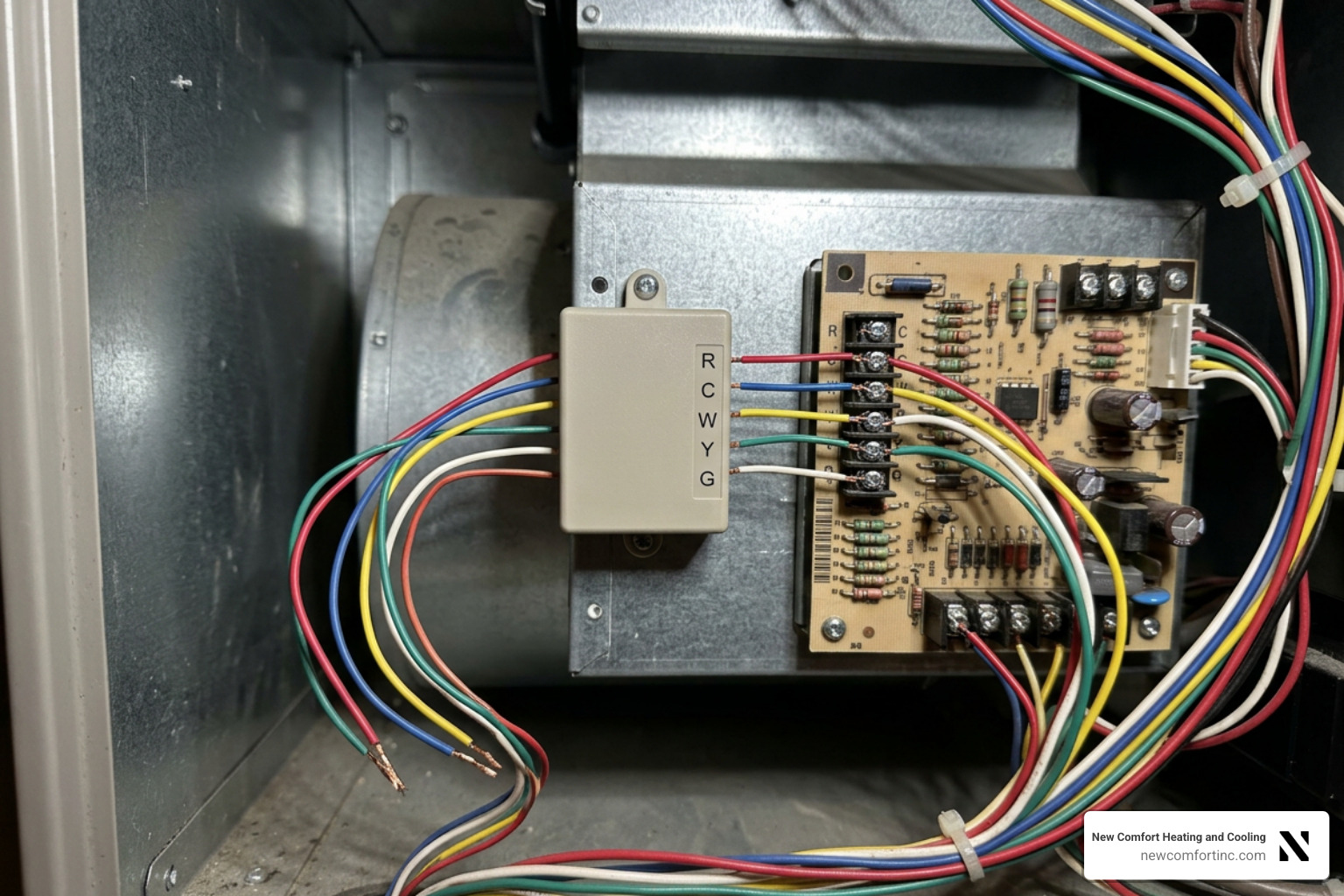
Wiring your new thermostat is straightforward when following the appropriate setup scenario for your home. We will cover the three main installation configurations: standard C-wire setups, non-C-wire setups using the Power Extender Kit, and multi-speed or spliced system setups.
Scenario 1: Installing With an Existing C-Wire
If your existing thermostat cable already includes a functional C-wire, physical installation takes only minutes! Follow this wiring sequence at the backplate:
- Rc: Insert your primary Red power wire into the Rc terminal. On single-transformer systems (the vast majority of residential homes), power MUST go to Rc.
- C: Insert your Blue or Black Common wire into the C terminal.
- Y1: Insert your Yellow compressor wire into Y1 (for primary air conditioning or heat pump compressor).
- W1: Insert your White heat wire into W1 (for conventional furnace heat or heat pump auxiliary heat).
- G: Insert your Green fan wire into G.
- O/B: If you have a heat pump, insert your reversing valve wire into O/B.
Pro Tip: Never install jumper wires between Rc and Rh terminals on ecobee thermostats! Unlike older thermostats that required a physical metal bridge between Rc and Rh, ecobee backplates manage single and dual-transformer power routing automatically inside the device.
For full technical specifications on multi-stage heating or cooling setups (Y2, W2), review the ecobee Smart Thermostat Premium Installation Manual.
Once each wire is pushed into its spring terminal block, gently give every individual wire a light tug. If the wire slips out, press down firmly on the terminal release button, push the bare copper lead deeper into the slot, and release.
Before snapping the smart faceplate onto the backplate, take a pinch of plumbers putty or HVAC duct seal compound and seal the hole in the drywall behind the backplate. Unsealed wire holes allow warm or cold drafts from inside the wall cavity to blow directly across internal temperature sensors, which skews indoor temperature and humidity readings!
Scenario 2: Installing Without a C-Wire Using the Power Extender Kit (PEK)
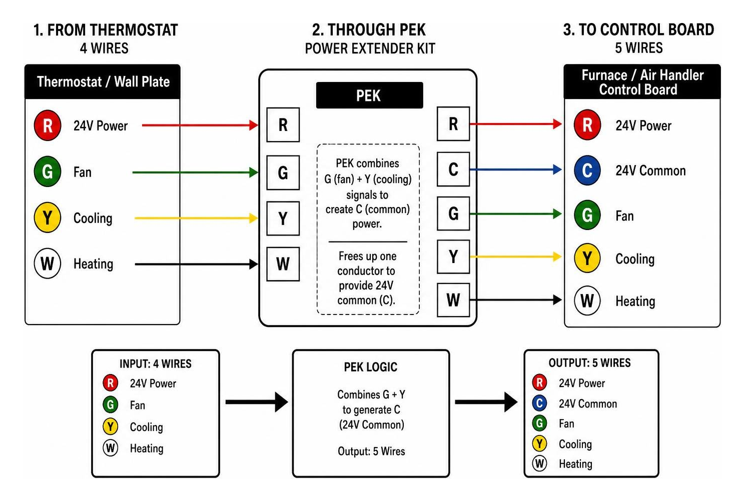
If you only have four wires (typically Red, White, Yellow, and Green) at your wall plate and no C-wire, do not worry! The included Power Extender Kit (PEK) safely combines the fan (G) and cooling (Y) control signals into a single wire, freeing up one conductor to act as your constant 24V power return.
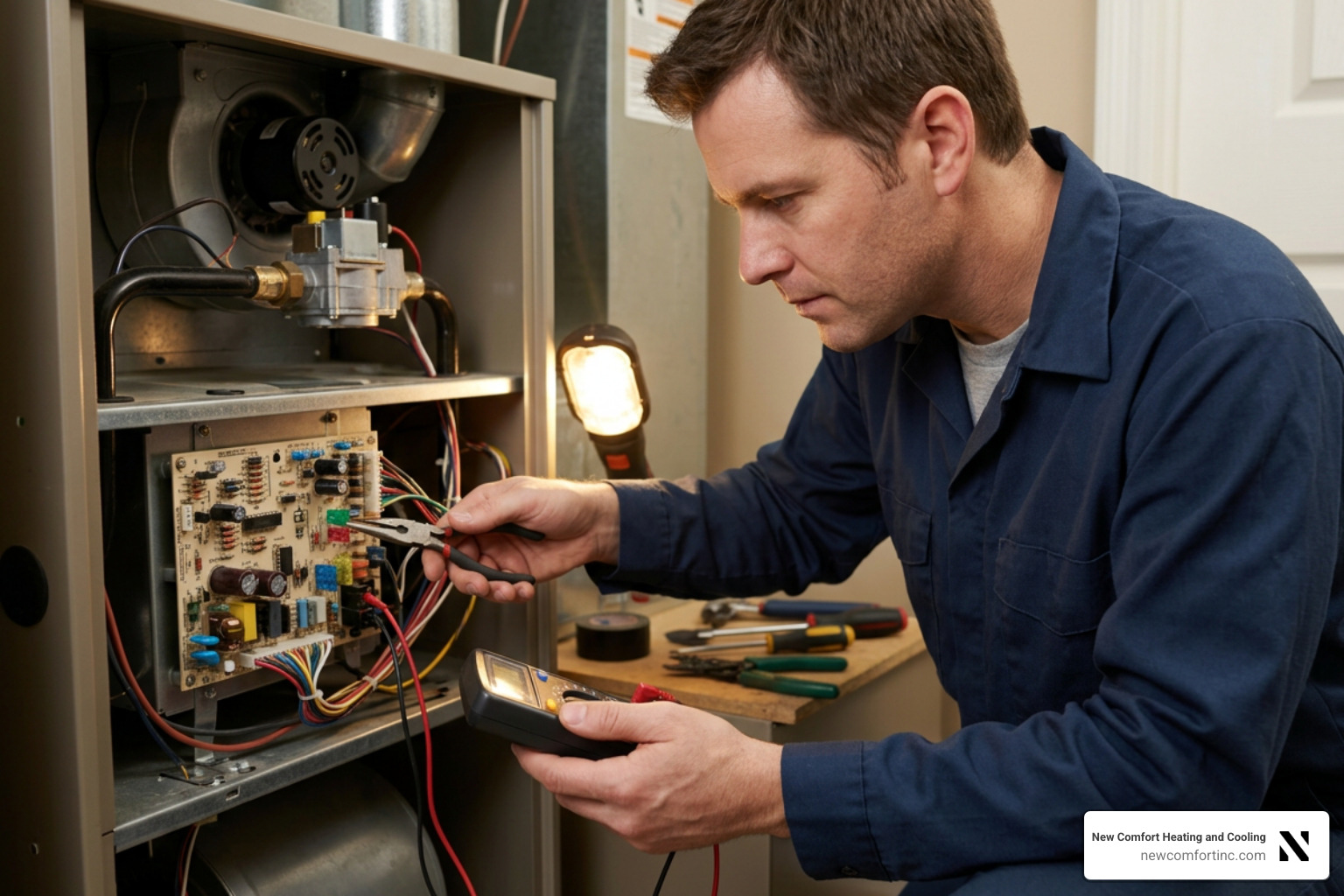
To install the PEK, you will work at your furnace or air handler's internal control board:
- Ensure power to the furnace is completely shut off at the breaker box.
- Open the main access door of your furnace or air handler to locate the control board terminal strip.
- Take a quick photo of the control board terminals showing existing wire connections.
- Disconnect the standard thermostat wires (R, G, Y, W) from the control board screw terminals. Note: If you have an outdoor air conditioner, leave the two separate compressor wires connected to the C and Y terminals on the furnace board!
- Connect those four disconnected thermostat wires into the matching labeled terminal block on the Power Extender Kit:
- Thermostat R wire to PEK R terminal
- Thermostat G wire to PEK G terminal
- Thermostat Y wire to PEK Y terminal
- Thermostat W wire to PEK W terminal
- Take the pre-wired 5-wire harness coming out of the opposite end of the PEK module and connect them directly into your furnace control board terminals:
- PEK R wire to Control Board R
- PEK C wire to Control Board C
- PEK G wire to Control Board G
- PEK Y wire to Control Board Y
- PEK W wire to Control Board W
- Secure the PEK module inside the furnace cabinet using the double-sided adhesive strip, making sure wires are clear of fan blades or heating elements. Reattach the furnace door panel securely.
Now head back upstairs to wire the ecobee backplate:
- Connect your R wire to Rc
- Connect your G wire (which now carries common power from the PEK) to C
- Connect your Y wire to the terminal labeled PEK+ on your ecobee Smart Thermostat Premium backplate
- Connect your W wire to W1
Scenario 3: Handling Multi-Speed Fans and Wire Splices
In some modern condos, fan coil units (FCU), or multi-speed systems, you may discover multiple fan wires labeled GL (Low speed), GM (Medium speed), or GH (High speed). The ecobee Smart Thermostat Premium natively supports multi-speed fan control. During initial startup, you will select the "I'm a Pro" setup option to map these fan speed wires to designated backplate terminals.
If your system uses a 2-pipe fan coil unit with a pipe temperature sensor, the ecobee uses water temperature thresholds (>83°F for heating calls, <65°F for cooling calls) to automatically switch modes.
If you open up your wall and discover that wire colors at your wall plate do not match wire colors connected at your furnace board, your system likely contains an intermediate wire splice. Splices frequently occur in homes where old thermostat wire bundles were extended during a previous remodel.
When an intermediate splice exists, trace the wire bundle out from the furnace control board to locate the wire junction. Install the PEK module directly at the splice location where the four thermostat conductors head up toward your living space walls, maintaining existing line continuity to outdoor AC equipment.
System Startup, Initial Configuration, and App Setup
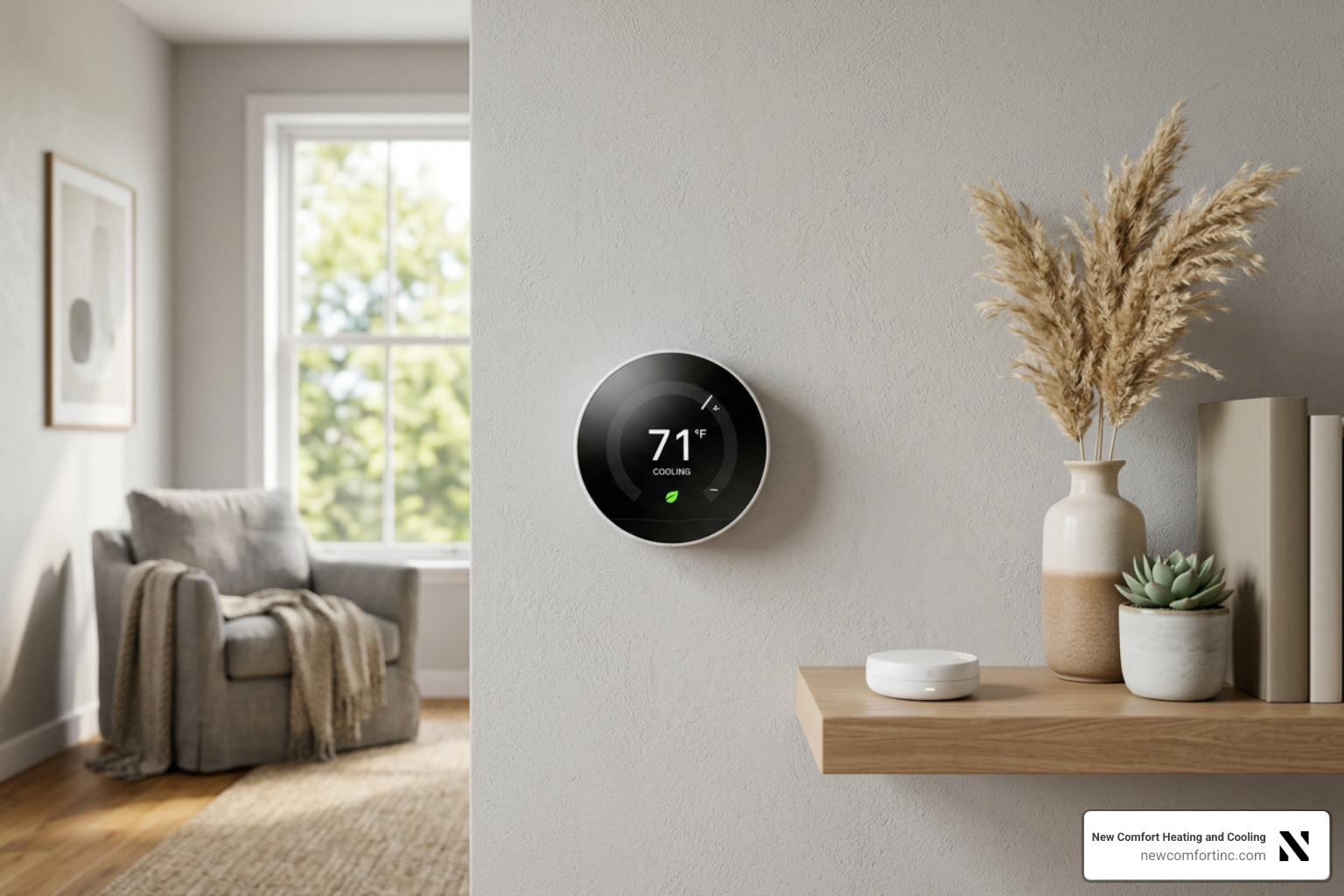
With all low-voltage wiring securely locked into terminal blocks, align the smart thermostat faceplate over the backplate and press firmly until it snaps into place.
Walk back to your circuit breaker panel and switch the HVAC breaker back ON. As 24VAC power flows into the unit, the lightbar across the top edge of your ecobee faceplate will momentarily flash green. This green flash is a visual indicator confirming that 24VAC power is present! The crisp display will turn on and begin booting up.
Wiring Detection, Calibration, and Registration
Upon first boot, your ecobee guides you through a clear, interactive setup wizard directly on its touchscreen:
- Terminal Auto-Detection: The ecobee automatically detects which wire terminals have conductors inserted. A screen diagram highlights active terminals. Verify that highlighted terminals match your physical installation. If a connected terminal is greyed out, press the terminal on screen to manually select and activate it.
- System Type & Valve Selection: Select whether you have a conventional furnace/AC system or a heat pump. If you have a heat pump system, select whether your O/B reversing valve energizes on cooling (most common, default for equipment like Bryant or Carrier) or energizes on heating.
- Heating Source & Fan Control: Specify whether your furnace or the thermostat manages fan operation during heating calls. Selecting furnace-managed fan control prevents the blower from pushing cool air through your vents before the heat exchanger warms up.
- Sensor Calibration: Once initial options are set, the thermostat screen enters a 20-minute temperature calibration cycle. During this time, internal sensors adjust to ambient room conditions. In addition, the onboard air quality sensor begins an automatic self-calibration cycle that takes up to 8 hours to complete without disrupting temperature control.
- App Pairing & Registration: Download the ecobee mobile app from the App Store or Google Play Store. Create a user account, tap "Add a Device", and select Smart Thermostat Premium. The thermostat screen will generate a unique 4-digit registration code under Main Menu > Gear Icon > Registration. Enter this 4-digit code into your mobile app within 60 minutes to complete cloud registration and link mobile remote controls. More info about thermostat services is available on our main site.
SmartSensor Placement and Accessory Integration
Your ecobee Smart Thermostat Premium includes a wireless SmartSensor. SmartSensors monitor both temperature and room occupancy, signaling the thermostat to eliminate hot or cold spots in high-priority living spaces.
To install your SmartSensor:
- Pull the plastic battery tab to activate the sensor (uses an included CR2477 coin cell with up to a 5-year battery life).
- Mount the sensor on an interior wall at a height of approximately 4 to 5 feet above floor level.
- Place it in a room you use frequently, such as a master bedroom or family room. Avoid placing sensors in direct sunlight, directly in front of air vents, or near drafty exterior doors.
- The SmartSensor communicates wirelessly using standard low-power RF up to a range of 60 feet, featuring an occupancy viewing angle of 140° horizontally and 100° vertically with accuracy up to 20 feet. Up to 32 SmartSensors can be paired with a single thermostat!
If your HVAC system includes integrated indoor air quality accessories—such as a whole-home evaporative or steam humidifier, dehumidifier, or Heat Recovery Ventilator (HRV)—you can connect those systems directly to the ACC+ and ACC- dry-contact terminals on your ecobee backplate.
Through the initial setup menu, select whether your accessory operates as a 1-wire or 2-wire setup. For dehumidification, configuring the "AC Overcool Max" feature allows your air conditioner to run past your target cooling setpoint by up to 3°F to strip uncomfortable humidity out of air during muggy summer months.
Frequently Asked Questions About ecobee Thermostat Premium Installation
Troubleshooting Your ecobee Thermostat Premium Installation
If your thermostat screen remains blank after restoring power, do not panic! Follow this reliable troubleshooting checklist:
- Check the HVAC Furnace Access Panel: Modern furnaces are equipped with a safety door switch (plunger switch) that cuts low-voltage power whenever the main access panel door is open or loose. Make sure your furnace panel door is completely flush and fully screwed in!
- Verify the Circuit Breaker: Double-check that your HVAC circuit breaker did not switch back to the tripped middle position when power was turned back on.
- Inspect R Wire Seat: Power off the breaker and remove the faceplate. Confirm that your main power wire is inserted into Rc (not Rh) and that the spring lever sits completely depressed.
- Inspect PEK Wire Harness: If you installed a Power Extender Kit, re-open your furnace door and double-check that every terminal screw on the PEK and furnace board is tight and clamping down on solid copper wire—not vinyl insulation.
- Check Installer Settings Access: If you ever need to access advanced equipment thresholds or override installer settings later on, enter the universal installer bypass code 3262.
For additional common cooling questions and equipment details, browse our extensive HVAC FAQ.
What Should I Do If My Wire Colors Do Not Match at the Furnace?
It is common in older homes across Chicago for wire colors at the wall plate to differ from wire colors at the air handler. This happens when builders installed intermediate splice junction boxes behind walls or inside attics.
Never assume wire functions based on color alone! Always trace wires from the furnace control board terminal screws outward to the splice box. Use a digital multimeter set to AC Voltage to test continuous 24VAC across wires. If a non-C-wire system uses spliced wiring, install your PEK module directly at the intermediate splice point where thermostat cables run up toward your living area.
How Do I Know If My System Is Incompatible With ecobee?
Your system is incompatible if you encounter any of these red flags during inspection:
- High Voltage Labels: Existing wire terminals marked L1, L2, 110V, 120V, or 240V.
- Thick Gauge Wires: Heavy gauge electrical wires connected with large wire nuts inside a deep electrical junction box behind your wall plate.
- Millivolt Systems: Gas fireplaces or wall heaters powered by two thin wires reading less than 1 Volt AC.
- 3-Stage Native Systems: Systems requiring 3 native stages of conventional compressor cooling (Y3) or 3 stages of conventional heating (W3) without internal control board staging algorithms.
Conclusion
Completing an ecobee thermostat premium installation is one of the most rewarding home upgrades you can make. By taking time to verify 24VAC system compatibility, cutting main electrical power safely, tagging existing wires, and configuring your PEK module or SmartSensors correctly, you ensure years of continuous, reliable climate control.
Homes that upgrade to smart energy control save up to 23% annually on heating and cooling costs while maintaining balanced whole-home comfort. Furthermore, ecobee hardware is protected by a 3-year limited warranty for total peace of mind.
If you run into complex HVAC wiring challenges, have a dual-fuel system, or simply prefer to have an expert handle the installation, our local team is standing by to help! Contact New Comfort Heating & Cooling for expert, friendly HVAC service in Chicago, IL, and Justice, IL. To learn more about our smart home control solutions or schedule professional installation, visit our Thermostats page today!