Thermostat Installation: A Quick, Safe Start
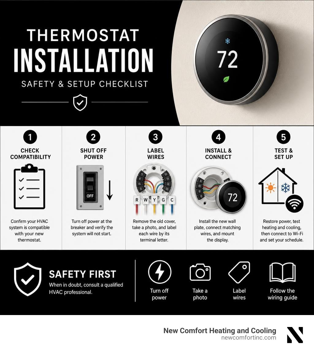
Thermostat installation usually takes 30 to 60 minutes when your home has a compatible 24-volt HVAC system and the wiring is clearly labeled. Before starting, turn off power to the furnace and air conditioner, confirm it is off, photograph the old wiring, label each wire by its terminal letter, and follow the new thermostat's wiring guide exactly.
- Check that your HVAC system and new thermostat are compatible.
- Shut off power at the breaker and verify the system will not start.
- Remove the old thermostat cover, photograph the terminals, and label wires.
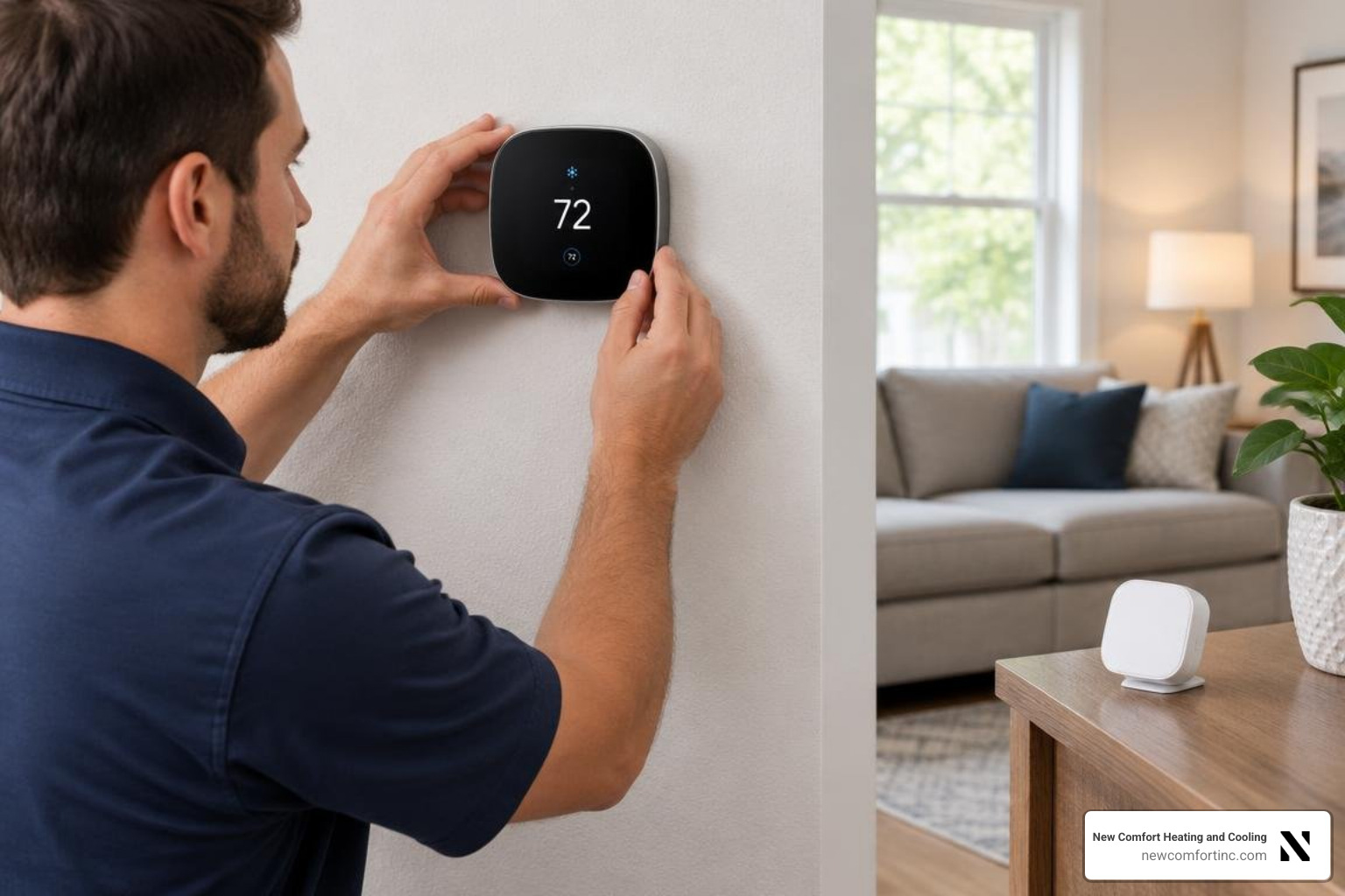
- Install the new wall plate, connect matching wires, and mount the display.
- Restore power, test heating and cooling, then connect a smart model to Wi-Fi and set your schedule.
A smart thermostat can make comfort easier to manage around a busy family schedule, but safe wiring matters more than speed. Line-voltage systems, missing power wires, heat pumps, and complex equipment may need a professional check before installation.
Evaluating HVAC Compatibility and the C-Wire
Before unboxing tools or taking your old unit off the wall, you must confirm that your heating and cooling equipment matches your new control board. Most modern residential homes in the Chicago area utilize standard low-voltage systems operating on 24 VAC (volts alternating current). However, attempting to hook up a low-voltage digital or smart thermostat to a high-voltage system can instantly fry the device's sensitive internal circuit board or create a serious electrical fire hazard.
| Feature | 24V Low-Voltage HVAC Systems | 110V–240V Line-Voltage Systems |
|---|---|---|
| Common System Types | Central forced-air furnaces, AC units, heat pumps, hydronic boilers | Electric baseboard heaters, radiant wall units, direct plug-in space heaters |
| Wiring Characteristics | Multiple thin wires (usually 18–22 gauge) in various colors | 2 to 4 very thick, heavy gauge wires joined with large wire nuts |
| Power Supply | Step-down transformer supplying 24 VAC | Direct household current (110V, 120V, or 240V) |
| Smart Compatibility | Compatible with almost all smart and programmable models | Incompatible with standard 24V smart units; requires specialized line-voltage controllers |
How to Check HVAC System Voltage and Compatibility
Checking your system's underlying electrical setup prevents costly mistakes. Take a close look at your existing wall unit. If you see warnings marked 110V, 120V, or 240V, or if removing the cover exposes thick, heavy-gauge wires capped off with twist-on wire nuts, you are dealing with a line-voltage setup. Line-voltage heaters require specialized line-voltage digital controls rather than standard smart thermostats.
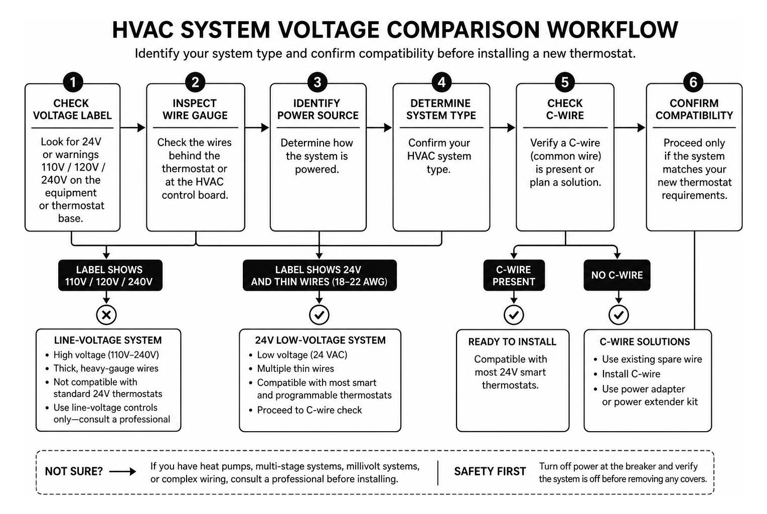
Additionally, inspect the physical wire strands. Standard 24V low-voltage control circuits rely on solid copper wiring. If your wall cavity contains stranded wires (cables made up of multiple tiny braided strands), your system is incompatible with standard quick-connect terminal ports. Similarly, proprietary multistage systems, wood/coal solid fuel burners, and low-power millivolt systems (frequently found in unpowered floor or wall gas heaters that generate their own tiny electrical currents) cannot supply the power required by modern Wi-Fi devices.
If you are unsure whether your setup features a multi-stage heat pump, conventional furnace, or unique wiring scheme, taking a moment to review our comprehensive HVAC FAQ can help clarify how different heating and cooling configurations operate.
Understanding the C-Wire and Common Wire Solutions
The common wire, universally known as the "C-wire," delivers continuous 24 VAC power to modern electronic controls. Older manual or basic programmable thermostats only drew small bursts of electricity to trigger relays, relying on backup AA or AAA batteries to power their basic LCD screens. Modern Wi-Fi thermostats, by contrast, maintain full-color illuminated displays, constant Wi-Fi connectivity, and background diagnostic routines. That ongoing workload requires a steady, reliable loop of current back to the furnace transformer.
If you peel back your old wall plate and do not spot a wire connected to the "C" terminal, do not panic! You have several viable options:
- Unused Wire Bundle: Often, installers pull a 5-conductor wire bundle through the wall even if the old unit only needed four wires. Check inside the wall cavity behind the baseplate; an unused wire strand (frequently blue or black) might be tucked away waiting to be connected at both the wall and the HVAC control board.
- C-Wire Adapter / Power Extender Kit (PEK): Many smart thermostat manufacturers include or sell an add-on adapter. Installed directly inside your furnace cabinet, this small module splits power from the existing "R" and "G" wires to simulate a dedicated C-wire without requiring you to fish new cables through finished drywall.
- Plug-In 24V Transformer: For heat-only setups (such as hydronic radiators), you can plug an external 24-volt transformer into a nearby wall outlet and run thin lead wires directly into the thermostat power terminals.
Consulting a standard Universal Thermostat Installation Guide provides clear visual schematics on how transformer power loops function during physical wire installation.
Essential Preparation for Thermostat Installation
Taking a methodical approach ensures your thermostat installation project runs smoothly without blowing a single low-voltage fuse inside your furnace circuit board.

Tools and Materials Required for DIY Thermostat Installation
Gather your supplies in one spot before starting. Having everything within arm's reach prevents running back and forth to the garage mid-project:
- Precision and standard screwdrivers: Small flathead and Phillips screwdrivers (sizes #0 through #2) for terminal screws and mounting bracket screws.
- Non-contact voltage tester: An essential electrical safety device to verify power is completely cut to the wall plate.
- Masking tape and pre-printed wire labels: For marking every disconnected cable strand according to terminal letters.
- Drywall anchors and mounting screws: To secure the new mounting bracket firmly against the drywall.
- Miniature bubble level: Standard on many baseplates, or handy as a pocket tool to ensure straight mounting.
- Hand held pencil: Perfect for wrapping loose wires around so they don’t slip back into the dark depths of your wall cavity.
Power Off Safety and System Shutdown Steps
Safety comes first. Never disconnect or touch control wires while electrical power is running to your equipment. Even low-voltage 24V lines can accidentally touch, sparking and immediately popping the delicate 3-amp or 5-amp fuse on your main furnace control board.
- Locate your main circuit breaker box: Switch off the dedicated circuit breakers powering both your furnace (heating unit) and your outdoor air conditioner compressor.
- Toggle localized power switches: Most indoor furnaces in home basements or utility closets feature a standard light-switch toggle right on the side of the unit housing. Flip this toggle switch off as an extra layer of protection.
- Perform a setpoint verification test: Head back to your existing wall unit. Adjust the target temperature setpoint 5 degrees past room temperature (higher in heating season, lower in cooling season).
- Wait a full 5 minutes: Modern HVAC machinery built into residential equipment features localized time delays that prevent rapid compressor cycling. If after 5 full minutes neither the outdoor fan nor the indoor blower turns on, your system power is successfully isolated.
- Verify with a non-contact voltage tester: Touch the probe tip against the terminals inside the old unit to guarantee zero live electrical current remains.
Removing Old Wall Plate and Wiring Disconnection
Now that your workspace is safe and powered down, you are ready to remove the old housing and document how the existing system was wired.
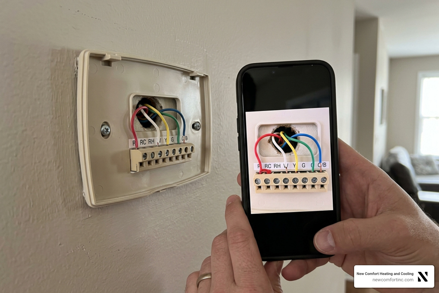
Safely Removing Old Display and Photographing Terminal Wiring
Gently snap or slide off the decorative outer faceplate of your old unit. Most models pop straight off their wall sub-base, though some older units utilize hidden latching buttons or tiny set-screws along the lower rim.
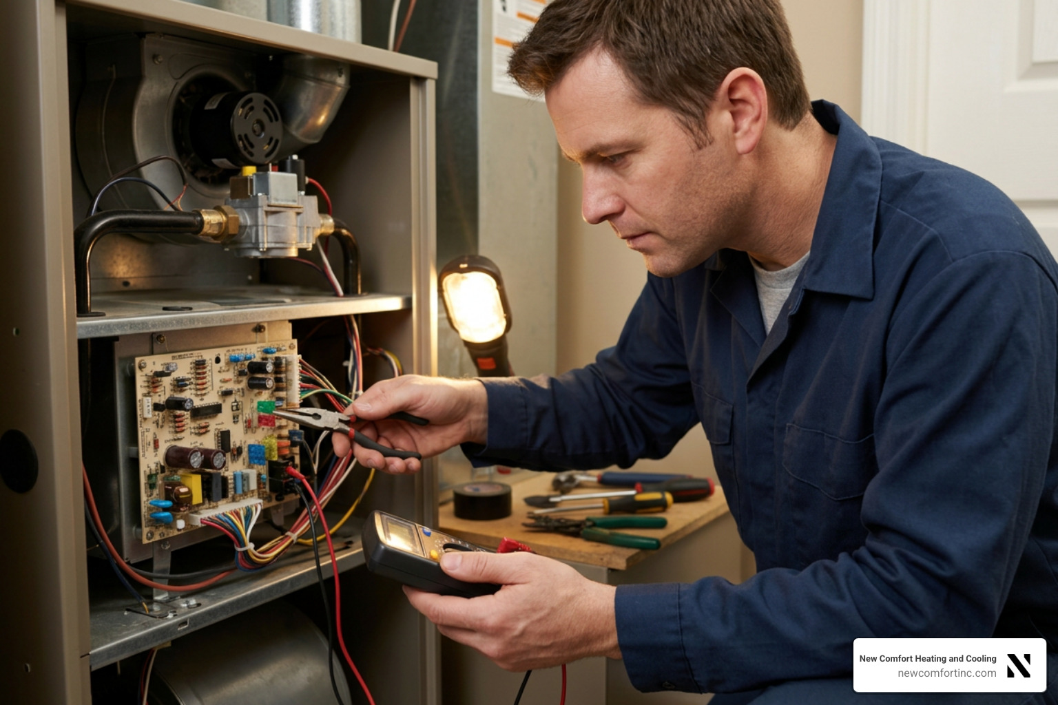
Once the terminal block is exposed, resist the urge to immediately start pulling wires out! First, grab your smartphone and take several crisp, well-lit photos of the existing wiring setup from different angles. Make sure the letter labels stamped into the plastic next to each terminal screw (such as R, Rc, Rh, G, Y, W, C, or O/B) are clearly legible in your photos. These reference photos serve as your ultimate backup blueprint if you need to double-check wire assignments later.
If you spot a short wire snippet bridging two ports together—such as a small metal wire jumper connecting terminal R to terminal Rc—make a mental note of it. Modern smart thermostats rely on internal electronic switches to bridge power terminals, so you will usually discard these old manual jumper wires.
Labeling Wires and Removing Mounting Hardware
Never label your wires based on their insulation color alone! While HVAC installers generally follow standard color conventions (Red for 24V power, Green for indoor fan relay, Yellow for cooling compressor, White for primary heat), previous contractors or DIY owners may have used whatever color wire bundle was on hand.
Always label each wire based on the terminal letter it is currently screwed into on the old plate:
- Apply pre-printed sticker labels: Wrap a matching adhesive letter flag (such as "Y" for yellow terminal, "G" for fan) onto each individual wire strand about an inch back from the terminal post.
- Loosen terminal screws: Use your precision screwdriver to back out the small terminal screws, releasing the exposed copper tips.
- Use the pencil wrapper technique: As you disconnect each wire, gently wrap the exposed copper end around a standard wooden pencil or pen. This clever trick keeps the group of loose wires bound together so they cannot accidentally slide backward through the drilled drywall hole into the wall interior.
- Unscrew old wall plate: Remove the mounting screws holding the old sub-base to the drywall. Slide the plate off the wire bundle and set it aside. If your home has an older glass-tube mercury thermostat, handle it carefully to avoid cracking the sealed bulb, and set it aside for local hazardous waste recycling.
Installing New Plate and System Configuration
With the wall prepped and cleared, physical assembly of your new control baseplate can begin.
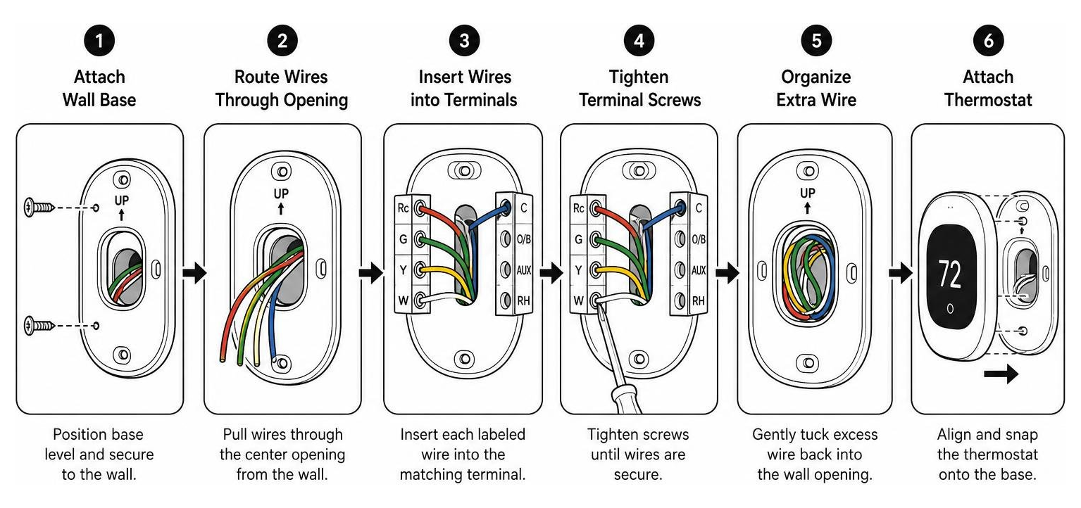
Follow the official Manufacturer Installation Guide to cross-reference terminal mappings tailored specifically to your model's hardware revision.
Completing the Physical Thermostat Installation and Mounting
If your old unit left behind an unpainted rectangular patch of drywall or oversized screw holes, install the decorative trim plate included with your new device.
- Position the new wall base: Thread the labeled wire bundle carefully through the center opening of the new baseplate or trim plate assembly.
- Level the bracket: Hold the plate against the wall. Align the built-in bubble level (or set your pocket level along the top flat edge) until the indicator bubble rests precisely between the black guidelines.
- Mark and drill anchor holes: Mark your screw locations with a pencil. If you are not hitting a solid wood wall stud, drill 7/32-inch pilot holes and tap plastic drywall anchors flush into the wall surface using a light hammer.
- Mount securely using hand tools: Secure the baseplate to the wall using the supplied mounting screws. Crucial rule: Always use a manual hand screwdriver—never a power drill! Over-tightening mounting screws with a power driver can easily crack the fragile plastic baseplate and damage underlying print circuits.
- Insert terminal wires: Push each bare copper wire end straight into its corresponding terminal slot (R into R/Rc, G into G, Y into Y1, W into W1, C into C) until the spring-loaded release button stays fully depressed. Verify that roughly 3/8-inch of bare copper is clean and straight before insertion; trim back any frayed ends with wire cutters.
Restoring Electrical Power and App Setup
Once every wire is fully seated flush against the base, bundle excess wire slack and gently press it back into the wall hole to prevent air drafts from blowing out of the drywall and throwing off room temperature sensor readings.
- Attach the front display: Align the electronic pin connectors on the back of the display unit with the baseplate socket and press firmly until it clicks into place.
- Restore main electrical power: Flip the localized furnace toggle switch back to ON, then switch on the central circuit breakers at your breaker panel.
- Monitor initial startup: You should see the screen light up or exhibit a pulsing charging light indicator. If your unit relies on internal lithium battery power, allow it a few minutes to top off its charge directly from the newly connected 24V transformer lines.
- Connect to Wi-Fi network: Follow the display prompts to select your home network. Almost all smart home controls require connection to a standard 2.4 GHz Wi-Fi band rather than a 5.0 GHz frequency.
- Pair with companion mobile app: Open your manufacturer smart app on your phone, scan the QR code located on the box or hardware screen, and establish your account credentials.
If you run into any hiccups pairing your mobile phone or establishing automatic energy-saving geofence schedules, reviewing Smart Thermostat Setup Support walks you through app pairing, remote Wi-Fi troubleshooting, and setting weekly program routines.
Testing Your Thermostat Installation and Programming for Savings
Once the display powers up and connects to Wi-Fi, take ten more minutes to confirm the thermostat installation actually controls every part of your system. A quick functional test now prevents a surprise no-heat call on the first cold night.
Run a Quick Function Test
- Heating: Set the new thermostat to Heat and raise the setpoint 3 to 5 degrees above room temperature. The furnace or heat pump should start within a few minutes, and warm air should follow once the burners or compressor get going.
- Cooling: Switch to Cool and lower the setpoint a few degrees below room temperature. Many thermostats add a built-in compressor delay of up to 5 minutes, so be patient before assuming something is wrong.
- Fan: Set the fan to On and confirm the blower runs without a heating or cooling call.
- Heat pump reversing valve: If you have a heat pump, verify that Heat mode delivers warm air and Cool mode delivers cool air. If they are reversed, the O/B setting in the installer menu likely needs to be changed.
If any mode fails to respond, turn the power back off and compare your thermostat wiring to the photo you took of the old unit. A loose conductor or a wire landed on the wrong terminal is the most common cause.
Program a Schedule That Fits Chicago Weather
A smart thermostat only saves energy if it is set up to match your routine. In Chicago's western and southwest suburbs, winter setbacks overnight and while you are at work deliver the biggest savings, while gentle summer setbacks keep the AC from running hard in an empty house.
- Set lower heating temperatures while you sleep or are away, and a comfortable temperature for mornings and evenings.
- Use geofencing or occupancy sensing if your model supports it, so the schedule adjusts when plans change.
- Avoid extreme setbacks on heat pumps during deep cold snaps, which can trigger expensive auxiliary heat.
- Review the energy reports in your app after the first month and fine-tune the schedule.
The ENERGY STAR smart thermostat guide explains which features help certified models save energy. If you would rather have a professional handle the wiring, C-wire, or system configuration, call New Comfort Heating and Cooling at (708) 717-9995.
Frequently Asked Questions About Thermostat Replacement
Replacing a thermostat is a straightforward project, but it is completely normal to have a few questions along the way. Here are clear answers to common DIY questions.
How do I know if my system power is fully switched off?
Never rely solely on circuit breaker label tags, as electrical panels are sometimes labeled incorrectly.
The absolute best way to verify that power is off is a simple two-step check: first, adjust your existing setpoint by at least 5 degrees past room temperature and wait 5 minutes to confirm no fan or compressor noise starts up. Second, touch a calibrated non-contact voltage detector tip against the "R" (power) terminal wire inside the wall plate. If the tester does not light up or chirp, electrical power is fully disconnected.
What should I do if my existing wall setup lacks a C-wire?
If your existing wall setup lacks a dedicated C-wire, do not despair! You have three reliable paths forward:
- Check for an unused conductor: Inspect the bundle behind your current wall plate. If there is a spare wire tucked into the wall, connect it to the C terminal on the wall unit and the C terminal on the indoor furnace control board.
- Install a C-wire power adapter: Buy an add-on adapter kit. Installing this small puck-shaped module inside your furnace blower cabinet re-routes existing wires to supply continuous power without running new cables through walls.
- Use a plug-in 24V wall transformer: For heat-only or simple two-wire setups, a plug-in 24VAC adapter supplies continuous power via standard wall outlets.
When should I call a professional technician?
While standard low-voltage replacements make great weekend projects, certain complex situations call for professional HVAC expertise:
- Line-voltage setups: If your home utilizes 110V–240V electric baseboard heat with heavy wire nuts.
- Complex dual-fuel systems: Systems combining an electric outdoor heat pump with a backup gas or oil furnace require precise staging logic setup to avoid damaging heat pump valves.
- Stranded or damaged wall wires: Braided stranded wires or old decaying insulation require fresh wire pulls to ensure reliable connections.
- System non-responsiveness: If power is restored but your air conditioner or blower refuses to cycle on, you may have an underlying relay or equipment fault.
If you encounter unexpected wiring issues or if your cooling equipment acts up post-installation, relying on professional Cooling - AC Repair guarantees your entire heating and cooling ecosystem runs smoothly without risk to your home.
Conclusion
Completing a DIY thermostat installation is one of the most cost-effective home upgrades you can tackle. In under an hour, you can transform how your home manages daily heating and cooling, unlocking enhanced energy efficiency, intuitive mobile scheduling, and continuous indoor comfort.
By taking the time to test system voltage, shut off circuit power, photograph terminal layouts, and correctly map out your C-wire power requirements, you ensure your equipment operates reliably season after season.
Of course, if you run into unexpected wiring, operate a complex multi-stage heat pump, or simply prefer having an expert handle the setup, our experienced technicians at New Comfort Heating & Cooling are here to help. Explore our complete range of smart climate control upgrades by visiting our Services - Thermostats page, or give our team a call anytime for fast, reliable local service across Chicagoland!