Step-by-Step Honeywell Thermostat Configuration and ISU Access
To configure a Honeywell thermostat, enter the Installer Setup (ISU) menu and match the equipment parameters to your physical HVAC system. On T-Series models such as the T4 Pro and T6 Pro, press and hold the Menu button for about 3 to 5 seconds until the advanced options appear, then select ISU and press Select. On smart touchscreen models like the T9 and T10, tap Menu, scroll to Advanced Settings, and choose Modify Configuration. Once inside, verify the system type, furnace efficiency, reversing valve orientation, and compressor protection settings before making changes.
Getting your heating and cooling equipment to run smoothly starts under the hood in the Installer Setup (ISU) menu. While everyday adjustments like turning the target temperature up or down are straightforward, the deeper installer parameters tell the wall unit what kind of physical equipment is connected in your utility closet or basement.
When you mount a modern Honeywell device onto its Universal Wall Plate (UWP), the low-voltage control wiring (R, C, W, Y, G, and O/B) communicates directly with your furnace, air handler, or air conditioner. Misconfiguring these settings can cause your system to blow warm air when you expect cooling, or short-cycle your equipment, driving up monthly operating costs by 15% or more. If you are starting from scratch with bare wires on the wall, review our guide on how to install your thermostat correctly in under an hour before adjusting advanced software parameters.
For most standard commercial and residential units, accessing this configuration area is built right into the interface. Official manufacturer documentation like the 5. Installer Setup (ISU) guide outlines the full matrix of codes. Let's walk through how to pull up these options safely on your screen.
Locating Your Model Number and Equipment Specs
Before you change any numbers in the menu, you must know the exact model installed in your home. The interface varies across product lines such as the T4 Pro, T6 Pro, T9, T10, and legacy FocusPRO models.

- Check the Digital Menu: On touchscreen and smart Wi-Fi models, press Menu, scroll to About or Device Info, and view the model number (typically beginning with RTH, TH, or T-series designations).
- Inspect the Physical Faceplate: Gently pull the thermostat body straight off its wall subbase. On the back sticker of the detached unit, you will find the complete model number and date code.
- Verify the Equipment Plate: Walk to your furnace or heat pump and check the manufacturer nameplate to note the heating type (gas, electric, oil) and efficiency rating.
If your wall unit's label is faded or missing, you can look up specific interface styles using the official Honeywell Thermostat Programming support page to match your screen layout with the correct technical manual.
Entering the Modify Configuration Menu
Once you know your model, you can access the configuration screens:
- T-Series Models (T4 Pro, T6 Pro): Press and hold the Menu button for approximately 3 to 5 seconds until the screen shifts to show advanced options. Select ISU on the screen and press Select.
- Smart Touchscreen Models (T9, T10, X8 Series): Tap Menu in the lower corner of the screen, scroll down to Advanced Settings, and select Modify Configuration.
- Legacy Push-Button Models (FocusPRO/VisionPRO): Press and hold the System button and the center blank button (or the two outer buttons) simultaneously for 5 seconds until two numbers appear on the screen.
Some digital smart models will require a 4-digit PIN. If prompted, the default PIN is often the 4-digit date code printed on the back of the faceplate, or 1234 on certain commercial software builds.
Core HVAC Equipment Settings and Cycle Rates
Selecting the right system type in the configuration menu prevents equipment conflicts. When you set parameters like ISU 2000 (System Type), you specify whether the wall unit is controlling a conventional forced-air split system, an air-source heat pump, a boiler, or a cool-only package unit.
| System Parameter | Typical ISU Code | Recommended Setting | System Impact |
|---|---|---|---|
| System Type | ISU 2000 | Conventional Forced Air (1) or Heat Pump (2) | Activates correct relay logic for cooling and heating stages |
| Furnace Efficiency | ISU 205 | Standard Gas (80%) vs. High-Efficiency (90%+) | Determines default heating cycle rate (CPH) |
| Reversing Valve | ISU 2060 | O (Cooling) or B (Heating) | Dictates whether O/B terminal energizes in cool or heat |
| Compressor Protection | ISU 2140 / 300 | 5-Minute Minimum Off-Time Delay | Prevents damaging compressor short cycles |
| Cooling Setpoint Limit | ISU 4100 / 420 | Minimum 50°F to 60°F | Prevents evaporator coil freeze-up |
Getting these parameters right ensures that your compressors, burner assemblies, and blower motors engage in the proper sequence without unnecessary component stress.
Gas Furnace Efficiency (ISU 205) and Cycles Per Hour
For conventional forced-air gas heating, the ISU 205 (Heating Equipment Type) setting is critical. This configuration determines the cycles per hour (CPH or CPM) that the thermostat calls for heat:
- Standard Efficiency Gas Furnaces (80% AFUE): Setting ISU 205 to standard gas configures the thermostat to run at 5 cycles per hour by default. Standard-efficiency heat exchangers warm up quickly and shed heat rapidly, benefiting from steady cycling to avoid wide room temperature swings.
- High-Efficiency Condensing Gas Furnaces (90%+ AFUE): Setting ISU 205 to high-efficiency adjusts the default cycle rate to 3 cycles per hour. High-efficiency systems require longer burner run times to establish stable draft pressure, maintain higher condensation efficiency, and protect the heat exchanger from thermal stress caused by rapid starts and stops.
Setting a high-efficiency furnace to 5 CPH can lead to frequent short-cycling, increasing component wear without improving indoor comfort.
Heat Pump Honeywell Thermostat Configuration and Reversing Valve Setup
Configuring an air-source heat pump requires particular attention to the changeover reversing valve. The reversing valve changes the direction of refrigerant flow to switch the indoor coil between heating and cooling modes.
- Locate Reversing Valve Setting (ISU 2060): Refer to the Setup options in your manual to set the valve orientation.
- Select "O" (Energize on Cool): Most major heat pump brands energize the reversing valve in cooling mode.
- Select "B" (Energize on Heat): Certain manufacturers (such as Rheem and Ruud) energize the reversing valve during heating calls instead.
If your heat pump blows hot air when calling for air conditioning, the reversing valve is almost certainly set to the opposite letter. Set your auxiliary heat lockout and backup heat sources correctly in the menu so that costly electric resistance heat strips only run when outdoor temperatures drop below the system's balance point.
Maximizing Energy Savings in Desert Climates
Extreme climate conditions put heavy demands on residential cooling systems. When outdoor ambient temperatures consistently climb past 100°F or dip during cold winter nights, proper configuration prevents runaway utility bills.
A thermostat calibrated incorrectly by just two degrees can increase monthly energy bills by 10%. Homeowners who select and calibrate their systems properly—or upgrade via professional smart thermostat selection—maintain consistent indoor comfort while managing equipment load.
Optimizing Your Honeywell Thermostat Configuration for Extreme Heat
During severe summer weather, setting the thermostat to 68°F does not make your air conditioner blow colder air; it only forces the compressor to run continuously during the hottest hours of the day.
- Target Setpoints: Set cooling to 78°F when occupied and allow a setback to 85°F when away or at work. According to the U.S. Department of Energy, adjusting your thermostat by 7 to 10 degrees for 8 hours a day can save up to 10% annually on cooling costs.
- Pre-Cooling Buffers: In areas with extreme heat, schedule your cooling cycle to begin 30 to 45 minutes before the hottest afternoon peak. Pre-cooling the living space during off-peak morning hours keeps the structure cool without forcing the compressor to fight peak afternoon thermal loads.
- Circulate Fan Mode: Instead of running the fan continuously ("On"), select the "Circulate" mode. This setting runs the blower fan randomly 20% to 30% of the time each hour, distributing conditioned air evenly without re-evaporating moisture from the drain pan back into the supply ducts.
Adaptive Intelligent Recovery and Schedule Overrides
Adaptive Intelligent Recovery (AIR, often found under ISU 4090) is a built-in algorithm that learns how long your specific HVAC system takes to reach target temperatures.
Instead of turning on the air conditioner right at 5:00 PM when your schedule changes from "Away" to "Home," AIR analyzes indoor temperature trends and starts cooling earlier. The system uses a gradual setpoint ramp rate (often around 2°F per hour) to smoothly bring the home to your target temperature by 5:00 PM. This controlled ramp reduces sudden mechanical strain on your compressor and avoids unnecessarily staging on auxiliary equipment.
Troubleshooting Display Messages, Holds, and Calibration
Thermostats provide clear status indicators when operating normally, but temporary overrides or protection timers can sometimes cause confusion.
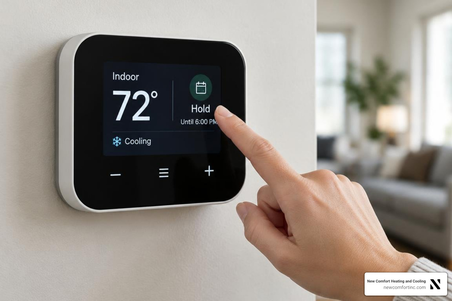
Understanding what your screen is reporting prevents unnecessary service calls and helps you get your scheduled programming back on track.
Clearing Temporary and Permanent Holds
When someone manually presses the temperature arrows, the thermostat suspends its normal program and displays a hold message:
- Temporary Hold: Overrides the schedule until the next programmed time period (for example, until "Sleep" begins). To clear this, press Run Schedule, Cancel, or Resume Program on the main screen.
- Permanent Hold: Locks the selected temperature indefinitely until manually released. To remove a permanent hold, tap the hold button or select Run Schedule to return control to your automated daily timetable.
If your unit does not respond to screen presses, check whether Keypad Lockout is active in the advanced settings menu and unlock it using your PIN.
Resolving Flashing Cool On and Wait Status Delays
If the display reads "Wait" or shows a flashing "Cool On" or "Heat On" message, your HVAC equipment is not broken.
This indicator represents the built-in 5-minute compressor protection delay. When an air conditioner or heat pump shuts down, refrigerant pressures inside the closed loop need approximately 300 seconds to equalize. Starting the compressor against high head pressure can trip the circuit breaker or damage internal components.
The thermostat enforces this 5-minute countdown before sending 24V power out through the yellow (Y) cooling terminal. If the message continues flashing for longer than 10 minutes, check for a low battery alert, verify that the furnace door switch is closed, or confirm that your 24V transformer is supplying power.
Frequently Asked Questions About Honeywell Thermostat Setup
For additional maintenance guidelines, browse our answers to common home climate questions for practical home comfort tips.
Why is my Honeywell thermostat flashing "Cool On" or displaying "Wait"?
A flashing "Cool On" or static "Wait" message is a normal safety feature. The thermostat enforces a mandatory 5-minute delay to allow system refrigerant pressures to equalize before restarting the compressor. If the message does not turn solid after 5 to 7 minutes, inspect your home's air filter, verify that the outdoor disconnect switch is on, and replace the thermostat's backup batteries.
Can I install and configure a smart Honeywell thermostat without a C-wire?
Approximately 30 percent of homes built before 1995 lack a dedicated C-wire (24-volt common wire) running from the furnace control board to the thermostat location. While some battery-powered programmable thermostats run without one, smart Wi-Fi models require continuous power. You can install an add-a-wire power adapter kit at the furnace control board or use the existing G (fan) wire as a common line if you do not run a fresh thermostat cable.
When should I call a professional HVAC technician for thermostat calibration?
You should contact an HVAC technician if:
- The displayed temperature is off by more than 3°F compared to an independent digital thermometer and internal offset calibration does not correct it.
- The system blows cold air when set to heat (or hot air when set to cool), even after checking reversing valve settings.
- The thermostat repeatedly resets to factory defaults due to low-voltage power drops.
- You are setting up a multi-stage heat pump with dual-fuel gas auxiliary heat and need to configure precise balance points.
Conclusion
Proper thermostat configuration ensures that your heating and cooling equipment runs smoothly, protects key mechanical parts, and keeps energy use under control through every season. By finding your model number, matching the ISU settings to your physical equipment, and programming realistic temperature setpoints, you can keep your home comfortable year-round.
If you run into complex multi-stage wiring, need low-voltage troubleshooting, or want to explore advanced equipment options, review our guide on comprehensive smart thermostat setup and climate management or contact our team at New Comfort Heating & Cooling for reliable, energy-efficient HVAC solutions.